
Foundation Accessories for Pole and Mast Installation
Explore foundation accessories, anchor bolts, templates and installation solutions for poles and masts.
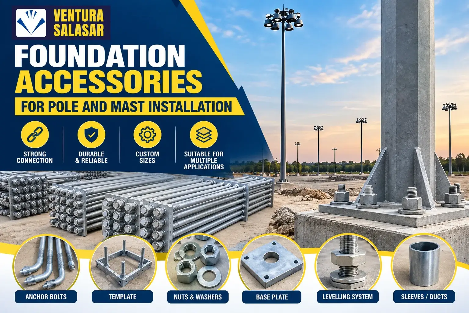
Foundation accessories transfer load between a pole or mast base and its concrete foundation while controlling alignment, level and connection integrity. Depending on the design, the package may include anchor or foundation bolts, nuts, washers, templates, sleeves, base plates, levelling arrangements, brace rods, sag rods, embedded plates and protective caps. These are structural connection components, not generic hardware.
A successful purchase starts with the approved base detail. Pole height alone is not enough to select anchor bolts. Wind loading, equipment weight and area, base-plate geometry, bolt circle, foundation type, concrete strength, soil capacity, corrosion exposure, fatigue and erection method all affect the design.
Ventura Salasar lists foundation accessoriesincluding non-standard anchor or foundation bolts, brace rods, sag rods and construction fasteners made to customer drawings and specifications. Buyers should send controlled drawings and require a dimensional compliance report for the actual order.
The main components in a foundation accessory package
| Component | Primary purpose | Important purchase check |
|---|---|---|
| Anchor or foundation bolts | Connect base plate to concrete foundation | Diameter, length, shape, grade, thread and embedment |
| Template | Hold bolts at the correct spacing and orientation | Bolt circle, hole size, rigidity and reference mark |
| Nuts and washers | Develop and retain the clamped connection | Grade, dimensions, quantity and coating |
| Base plate | Distribute mast or pole load into anchors and foundation | Thickness, holes, flatness and weld detail |
| Levelling system | Set elevation and plumb before final bedding | Approved nut or shim method and grout gap |
| Sleeves or ducts | Provide installation tolerance where designed | Size, location and approved grout or seal method |
Anchor and foundation bolts
Common shapes include straight, L and J configurations, while some designs use headed, plate-ended or fabricated anchors. Shape must not be chosen by familiarity. The structural engineer defines how tension and shear are transferred and the required embedment, edge distance and reinforcement interaction. Ventura states that it produces L, T, J and stiffened pipe-type arrangements as well as long brace rods; the project drawing should identify the exact geometry.
Templates and setting frames
A template holds the bolts in the correct bolt circle, spacing, projection and orientation during reinforcement fixing and concreting. A thin temporary ring may distort, while a rigid double-template frame can control both top and lower positions for demanding assemblies. The template should have a clear reference for door or bracket orientation and enough access for concrete placement and vibration.
Nuts, washers and thread protection
Specify the number and position of nuts, washer type, grade, dimensions, coating and tightening method. Some bases use levelling nuts beneath the plate; others use shims or direct bearing. Thread protectors prevent damage and concrete contamination before erection. Site teams should not chase damaged threads by aggressive grinding or substitute unmatched nuts.
How pole type changes the foundation connection
An octagonal pole for street lighting may use a compact base plate and anchor-bolt cage, while a high mast carries greater wind and equipment effects and may require a larger, more closely controlled foundation interface. Hinged poles, traffic structures, signage masts and stadium masts introduce different operational or fatigue demands.
Accessories should therefore be packaged by structure mark, not merely by nominal height. The delivery list should state pole or mast ID, foundation drawing revision, bolt-set number, template, nuts, washers and any embedded item. Mixed unlabelled hardware creates a high risk of installing a bolt cage intended for another base.
Inputs the structural designer needs
- Pole or mast geometry, base-plate drawing and material properties.
- Luminaire, bracket, headframe, antenna, sign or equipment area and weight.
- Site wind parameters, terrain, exposure and applicable design basis.
- Geotechnical report, groundwater level and allowable foundation criteria.
- Concrete strength, reinforcement arrangement and construction tolerances.
- Fatigue, vibration, seismic, accidental or operational loads where relevant.
- Corrosion environment, coating system and required design life.
- Erection method, access, crane plan and temporary stability arrangement.
When one input is provisional, the drawing should say so and define the approval hold point. Fabricating bolts before final base-plate and foundation coordination can lock the project into an avoidable mismatch.
Specifications that belong on the purchase order
Dimensions and tolerances
State bolt diameter, total length, unthreaded length, threaded length, end shape, bolt-circle diameter, projection above concrete, template spacing and permitted tolerances. Define whether dimensions refer to an uncoated or finished component. Include a controlled drawing instead of relying on a text description such as “M30 J bolt.”
Material and mechanical grade
The approved design should state the material standard and property class or grade. Ventura’s page lists several grades offered, but the buyer must not substitute a stronger-looking grade without engineering review: strength, ductility, weldability, coating process, thread manufacture and nut compatibility all matter. Material certificates should identify the ordered item and heat or batch where traceability is required.
Thread and nut compatibility
Define thread form, pitch, tolerance, thread length and whether threads are rolled or cut when the specification requires it. Nuts must run freely after coating without excessive play. Galvanizing changes dimensions, so the bolt, nut and coating process need coordination. Trial assembly before dispatch can identify binding or mismatched threads.
Corrosion protection
Coating selection depends on exposure and the project standard. Ventura provides hot dip galvanizing services, but the order should specify coating scope, thickness or governing requirement, venting/drainage for fabricated items, repair method and inspection. Avoid coating only the visible thread when the embedded or splash-zone details require a broader corrosion strategy.
Coordination between base plate, bolt cage and reinforcement
Create a combined section showing base plate, grout, bolt projection, sleeves, reinforcement, pedestal edges and conduit entries. This reveals clashes before concreting. The structural designer should check anchor spacing and edge distance while the civil team confirms that bars can be placed and concrete can flow around the cage without voids.
Electrical conduits and earthing conductors must not push the bolt cage out of position. Drain paths, access doors and high-mast raising mechanisms may also need a defined orientation. Use the template reference mark and survey controls to align these interfaces.
Factory quality checks before dispatch
| Check | Evidence | Why it matters |
|---|---|---|
| Material identity | Certificate and traceability mark | Confirms ordered grade |
| Overall dimensions | Inspection report | Confirms embedment and projection |
| Bolt circle/template | Trial assembly or jig report | Prevents base-plate mismatch |
| Thread fit | Matched nut trial | Avoids erection delay |
| Coating | Visual and measured inspection | Supports corrosion protection |
| Quantity and marking | Packing list by structure ID | Prevents site mixing |
A full-size template or base-plate gauge is valuable for non-standard work. If the actual pole base plate is available, perform a controlled trial fit. Mark every bolt set and keep nuts, washers and templates together. Protect threads with caps and support long rods so they do not bend during transport.
Site setting and concrete placement
1. Survey and secure the cage
Set the foundation centreline, elevation and orientation from approved survey points. Brace the cage against movement during reinforcement work and concreting. Do not rely on the reinforcement alone to hold projection and plumb unless the drawing explicitly provides that detail.
2. Check before the pour
Use a hold-point checklist for bolt circle, diagonals, verticality, projection, template elevation, orientation, reinforcement clearance, earthing and conduit positions. Confirm threads are protected and clean. Photograph the assembly with a scale and structure ID.
3. Control movement during concreting
Concrete discharge, vibration and workers standing on the template can move the cage. Monitor survey references during the pour. Place and vibrate concrete to avoid voids around anchors without striking or displacing them. Recheck position before initial set if the construction method permits correction.
4. Protect and re-survey after the pour
Keep threads protected during curing and nearby civil work. After sufficient strength is reached, remove temporary components only as designed, clean the exposed threads and conduct an as-built survey. Record any deviation and obtain written engineering disposition before attempting to bend, heat or force a bolt.
Base-plate levelling, grouting and tightening
The approved detail defines whether the base bears on non-shrink grout, levelling nuts, shims or another arrangement. Set the pole plumb without leaving an unintended flexible gap. Grout should fill the designed space continuously, support load transfer and allow drainage details to function. Surface preparation and curing follow the grout manufacturer’s instructions.
Tightening procedure depends on the connection design. “Tighten as much as possible” is not a method. Record the sequence, target and tool calibration where controlled tightening is specified. Recheck plumb and visible base condition after tightening. Do not use double nuts, tack welds or locking products unless included in the approved detail.
Installation problems and safe responses
| Problem | Unsafe shortcut to avoid | Correct response |
|---|---|---|
| Bolt circle does not match | Flame-cutting base-plate holes | Survey, quarantine and engineering review |
| Projection is too short | Using partial nut engagement | Assess approved extension or foundation repair |
| Bolt is bent | Heating and straightening on site | Engineering disposition and replacement plan |
| Thread is damaged | Grinding until the nut fits | Assess approved thread repair or replacement |
| Cage shifted in concrete | Forcing the pole into position | As-built survey and structural review |
| Grout has voids | Covering the edge cosmetically | Investigate extent and execute approved repair |
Deviation decisions must consider load path, fatigue, corrosion and maintainability. A modification that permits erection may still reduce the connection’s reliability. Keep a non-conformance report, calculations or approval, repair procedure and verification evidence in the handover file.
Transport, storage and handling before installation
Long bolts and brace rods can bend when lifted from one point or stacked without support. Templates can distort under other cargo, while exposed threads can be bruised by chains and forklift tines. Pack each set on a rigid support, protect threads, separate coated surfaces and keep identification visible. The receiving team should inspect quantity, straightness, thread condition and coating before accepting delivery.
Store accessory sets above standing water and away from cement dust, welding spatter and mixed site hardware. Do not remove nuts and washers for use elsewhere. If components are stored for an extended period, repeat the condition check before setting the cage. Any coating damage should be repaired using the approved system and recorded rather than hidden inside the foundation without review.
Inspection after the structure is erected
Inspect base-plate seating, grout, nuts, washers, exposed threads, coating, drainage, door orientation and plumb. Look for cracks, gaps, corrosion, loose hardware or unexpected movement. High masts and poles carrying dynamic equipment may need a defined follow-up inspection after initial operation.
Routine maintenance should preserve drainage, prevent soil or paving from burying the base, repair coating damage and investigate cracking or movement. If nuts are rechecked, follow the original connection procedure; arbitrary retightening can disturb load distribution.
How to compare supplier quotations
Normalize every offer against the same drawing revision and bill of materials. Compare material grade, dimensions, tolerance, thread, coating, certificates, template, nuts, washers, marking, trial assembly, packing, delivery and inspection. A low price may omit the template, matched nuts, coating repair or traceability that the project needs.
Ventura also offers structural designing services. When design input is requested, define whether the supplier is checking only the accessory drawing, the pole base, the full foundation or the complete structure. Assign responsibility and approval boundaries in writing.
Worked example: high-mast anchor cage
A logistics yard orders a high mast with a large base plate. The geotechnical report and wind design are completed before the foundation drawing is released. The approved accessory drawing identifies the bolt-set mark, bolt circle, embedment, projection, material, thread, nuts, washers, coating and a rigid two-level template. Conduit and earthing entries are shown on the same section.
At the factory, the supplier checks the cage in a jig and trial-fits a gauge matching the base plate. Each set is packed by mast number. On site, surveyors verify centreline and orientation before the pour and again after curing. The erector accepts the as-built survey before mobilizing the crane. This sequence costs less than discovering a mismatch while the mast is suspended.
Handover documents that protect the asset
Retain approved and as-built drawings, design inputs, material certificates, coating records, dimensional inspection, trial-fit evidence, packing list, concrete records, pre-pour checklist, survey reports, grout records, tightening report, non-conformance approvals and final photographs. Link each record to the structure ID. Ventura Salasar’s About Us pageprovides company background, while project acceptance must remain tied to the supplied items and documented checks.
Frequently Asked Questions
1. What are foundation accessories for poles and masts?
They are structural connection items such as anchor bolts, templates, nuts, washers, base plates, sleeves, brace rods and related embedded components. Final dimensions, materials, tolerances and installation details must follow the approved structural design, geotechnical data and project drawings.
2. Can anchor bolts be selected from pole height alone?
No. Wind, equipment, base geometry, soil, concrete, foundation design, corrosion and erection method also affect the connection. Final dimensions, materials, tolerances and installation details must follow the approved structural design, geotechnical data and project drawings.
3. Why is an anchor-bolt template needed?
It controls bolt spacing, bolt circle, projection and orientation while reinforcement and concrete work take place. Final dimensions, materials, tolerances and installation details must follow the approved structural design, geotechnical data and project drawings.
4. Are J bolts always suitable for lighting poles?
No. Bolt geometry and anchorage mechanism must come from the approved structural design. Final dimensions, materials, tolerances and installation details must follow the approved structural design, geotechnical data and project drawings.
5. Should anchor bolts be galvanized?
Use the corrosion-protection system stated in the project design, coordinated with thread and nut dimensions. Final dimensions, materials, tolerances and installation details must follow the approved structural design, geotechnical data and project drawings.
6. How much thread should project above the base plate?
Projection must accommodate the approved levelling, plate, washers, nuts and required thread engagement; it is drawing-specific. Final dimensions, materials, tolerances and installation details must follow the approved structural design, geotechnical data and project drawings.
7. Can misaligned bolts be bent into place?
Not without a written engineering procedure. Bending or heating can damage the bolt, coating and foundation interface. Final dimensions, materials, tolerances and installation details must follow the approved structural design, geotechnical data and project drawings.
8. What should be checked before concrete placement?
Check centre, orientation, bolt circle, diagonals, projection, verticality, reinforcement clearance, conduits, earthing and bracing. Final dimensions, materials, tolerances and installation details must follow the approved structural design, geotechnical data and project drawings.
9. Why should a bolt cage be trial assembled?
It verifies thread fit, spacing, template geometry and base-plate compatibility before delivery. Final dimensions, materials, tolerances and installation details must follow the approved structural design, geotechnical data and project drawings.
10. What is the purpose of grout below a base plate?
Where designed, it provides continuous bearing, fills the levelling gap and supports load transfer into the foundation. Final dimensions, materials, tolerances and installation details must follow the approved structural design, geotechnical data and project drawings.
11. How are supplier quotations compared fairly?
Compare the same drawing revision, materials, dimensions, accessories, coating, testing, documentation, packing and delivery scope. Final dimensions, materials, tolerances and installation details must follow the approved structural design, geotechnical data and project drawings.
12. What records are needed after installation?
Keep as-built surveys, material and coating evidence, concrete and grout records, tightening data, approved deviations and photographs. Final dimensions, materials, tolerances and installation details must follow the approved structural design, geotechnical data and project drawings.
Make the Foundation Connection Right Before the Concrete Sets
Foundation accessories are inexpensive relative to the pole or mast, yet a dimensional or material error can stop erection and compromise the load path. Ventura Salasar can manufacture foundation bolts, templates and related components to approved project drawings. Send the structure type, base detail, bolt-set drawing, grade, coating, quantity, delivery location and inspection requirements through the Ventura Salasar contact page for a controlled technical and commercial proposal.




Copyright © 2023-2026 Ventura Salasar | All Rights Reserved | Website Design, Developed & Google Promotion by VRD Creative Pvt Ltd